On Laundry
Of the various housework I have to do, laundry is actually not that bad. I have this great machine I bought a long time ago that does most of the work. I just have to remember to put things in it and we’re good. I have another machine that takes the clean things and transforms them into dry things. It’s a magical experience, tainted only by short attention span that leads me to forget to transfer the laundry from the cleaning machine to the drying machine.
I set out to solve this problem using my only skills, but I have a problem. How do I program an old washing machine?
Feeling It

My first idea was to use a vibration sensor attached to the laundry devices to detect when they’re doing something.
This is more complicated than it sounds because the vibration can be a bit subtle during some of the cycles and getting reliable signal out of these sensors at the levels I needed seemed just a little too indirect.
Power Measurement
“I know, I’ll just measure the power it’s using.”
I have awesome tools like the “Kill A Watt” that do much of what I need. I just need to get the data out. Adafruit has Tweet-a-Watt, which is a great concept, but really expensive, and still not doing exactly what I want. So I started looking into building my own.
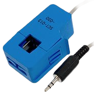
I looked around for the most basic thing I could find and found this cheap current transformer on Amazon. Of course, I had no clue whatsoever how to use a current transformer. I read a lot about them and there were lots of documents that made me feel like I was going to tear a hole in space and time if I didn’t properly cross the pins. This device is like the anti-Gozer.
As an uneducated software hacker, it took me a lot of trial and error to get the right circuit designed for this thing. At the time, I did a lot of the work on my iPad, using iCircuit which I strongly recommend. I used that to design (and test) the following circuit:
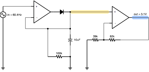
I can’t stress how useful iCircuit was. My notes are filled with readings from scopes where I had attempted something and didn’t quite get the right result. The cases that mattered most were sudden spikes, limits and endurance. Some of the circuits didn’t drain well, so they’d just kind of float up after a while.
I don’t use my iPad much since I got my Nexus 7. iCircuit was one of the tools I hoped I could replace. There were rumors of an Android version coming, but I couldn’t find anything concrete. I did, however, find EveryCircuit. This is a pretty great piece of software. It’s missing a couple of features I hope make it, but it also does a few things much better than iCircuit. It’s a grand age for making things.
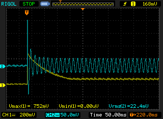
Once I got a circuit that was good in theory, it was time to breadboard it and try it with some real load.
As I mentioned above, I found that jolting the CT with a sudden load would call it to bounce way off the charts in early testing. This is sort of the electronic equivalent of a stack overflow, except instead of crashing my program, it burns down my house.
I had incentive to get this right.
There was a lot of simulated testing, then a lot of breadboard testing and then I wanted something I could actually deploy in my garage. I went over to halted and found some decent prototyping boards and ended up with something that was a bit more rigid than the breadboard.
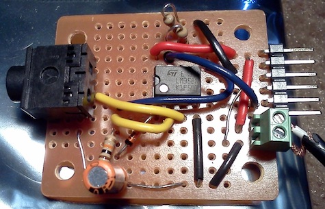
I don’t have a picture of the actual final product which is unfortunate. I went through a few different debugging strategies. First, I would look at things just through the console. That’s very inconvenient as the device is hooked up in my garage. The radio signal wasn’t always great, and I’d affect it by getting close to it (insert obvious Heisenbug joke). I added a light so I wouldn’t have to get too close and hook up a computer and stuff. Then I wanted to know more than one thing, so I’d have the light blink at different rates.
In the end, I hooked up a 2x16 character LCD so I could just print out whatever the sensor and radio states were. That was really helpful, but I damaged it in the final installation so that it’s basically useless now. It was good enough to get it going, though.
Building a Reader
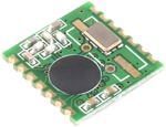
At this point, I have hardware that converts the magnetic field observed by the appliance’s power draw to 0-n volts. Originally I was aiming for 5V, but after looking at wireless options, I decided to give JeeNode a shot. They run at 3.3V, but are otherwise pretty much Arduino compatible, but featuring a small, low power and most interestingly, cheap radio - the rfm12b.
Getting things up and running was pretty easy. One problem I found in using these radios is that they’re pretty low-level. Robust protocols don’t come for free.
For this, my needs were pretty simple. The project evolved just a but, but essentially I send a packet out with an 8-bit sequence ID and I keep sending the same sequence ID until the other end responds. I really only want to know if the device has been on since the last time I looked, so I send the most recent reading off of the sensor and the highest value I’ve read since I received an ACK. Every transmission requests an ACK, but there’s often tons of interference (in both directions) so each side has to transmit and be heard by the other before the needle is moved.
Internally, the sensor updates every second. It transmits at least once every 10s and once on every change since the last ACKd value.
Making it Useful

On the reader side, I have a really simple read-only protocol that converts the stuff in the air to RS232 through a USB interface using a simple go program that does a few things:
- Serves the readings up over HTTP.
- Lights up stuff in my living room telling me the state of the laundry.
- Sends out alerts with NotifyMyAndroid so my phone and Nexus 7 start beeping when things change.
I had to start by creating an RS232 interface for go. I’ve been able to use this for a couple of projects now (hopefully I can write about one of the others, because it’s pretty awesome).
The NotifyMyAndroid interface for go alone has kept me from having to re-wash laundry that sat in the washer too long.
The source to the sensor, reader firmware and go parts are all available, though I can’t guarantee they’re 100% ready to deploy for anyone who isn’t me. If anyone wants to try something similar, I’ll gladly help, though.
