Playing with WS2812 LEDs

I’ve been playing with WS2812 addressable LEDs for a few days now. They’re kind of neat. You can read a lot about these in Adafruit’s Neopixel Überguide, but there are a wide variety of these things available and lots of interesting applications.
I ordered a handful from Adafruit last time I needed some stuff from there and finally got around to playing with them.
Of course, the first thing I did was wire them up and try to play with existing sketches. That was neat, but I wanted to figure out how hard it would be to deploy them into something else.
I came across this really great PicoC project for Tau Labs that embedded an attiny85 into a servo wire and used it to provider a higher level abstraction to interacting with the LEDs. I built one of these real quick (though changed the wire protocol slightly to allow me to address one pixel at a time).
Friday’s Projects

Josh.com had a nice informative post explaining a lot of details about other ways to play with them, which got me very interested in sniffing stuff out and see what’s going on should I try out a few of these alternative libraries.
This inspired me to write friday’s first project of the evening – a WS2812 Saleae Logic plugin. As seen in the screenshot above, this detects which lights should be which color at exactly what time offset as things go across the wire, both interactively above, and in an export allowing further processing.
So the obvious second project for Friday night was to write a playback tool for these recordings. The nice side-effect is that I was able to see what a particular program would look like on a longer strand of LEDs without having a long strand. I could just tell an arduino I had N LEDs and record the signal it sent out to the phantom LEDs (without even having to plug a single one in).
e.g., I only have 5, but my simulator let me see what 13 would look like on strandtest by running the actual program on my actual arduino. The result looks like this:
Initially, I was running the default configured for 60 LEDs. I certainly don’t have that many, but it makes a nicer demo.
Saturday
Saturday, I had dance recitals and other stuff, so I didn’t get much done. My biggest accomplishment was building a bit of code I could run on my attiny85 to allow PWM-based light mode selection. I coded up a couple of modes and had a simple table to select which mode based on the minimum PWM level (in μS) like this:
struct {
    unsigned long minVal;
    void (*mode)();
} modes[] = {
    {1500, flash},
    {900, pulse},
    {0, emergency},
};
This is a dumber version of the Tau Labs thing above, but it means it can work with dumber things, which is nice.
Sunday

Sunday, I ended up out driving most of the day. It was nice out. Not a lot of time again, but I did get to miniaturize the bits from yesterday.
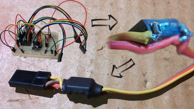
I had to hack together a 500Ω resistor out of two 1kΩ 0603 resistors I soldered together to attach the output signal wire. You can see the progress of this as it went from prototype on a breadboard, through the tiny soldering to the ready-for-consumer product (almost):

In the end, I have my mode selection on a wire, demoed below. Note “emergency” mode is when there’s no PWM signal at all, as in the beginning of this video (flash red). Then I switched to the servo tester to try varying the PWM level to see it hit different modes. As shown in the snippet above, “pulse” is on the lower end and “flash” is on the upper end. The names might not be useful, but you can see the difference in the demo.
I haven’t fully figured out what I want to do with the lights yet, but I’m having fun.
